Prepare DXF Files for Laser or Waterjet Cutting Without Extra Costs
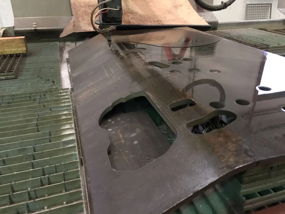
Why Clean DXF Files Save You Money
When you request a laser or waterjet cutting quote, the DXF file you send is more than a drawing—it’s the foundation of your part’s cost. A file with hidden geometry errors can trigger manual cleanup, extra programming time, or even scrapped parts, all of which inflate your final invoice.
Many engineers and buyers assume their CAD output is ready for production, but in practice, elements like open contours, duplicate lines, or microscopic gaps often slip through. These issues force the cutting service to pause, interpret intent, or request clarifications, adding revision rounds that delay delivery.
Understanding how to prepare a DXF file specifically for flatbed cutting processes puts you in control. A few minutes of verification on your side can mean the difference between a competitive, straightforward quote and a project burdened by non‑recurring engineering charges.
Geometry Hygiene: Open Contours, Duplicate Lines, and Micro Gaps
The cutting path follows exactly what your DXF defines. An open contour where a closed shape is expected may cause the machine to stop or, worse, produce an incomplete cut. In laser cutting, for instance, a shape that is not closed cannot be cleanly separated from the sheet, leading to manual finishing work.
Duplicate lines are equally problematic. Two identical lines stacked on top of each other will be cut twice, wasting cycle time and damaging the material edge. On waterjet machines, this double pass can widen the kerf beyond tolerance and increase abrasive consumption unnecessarily.
Tiny gaps between intended intersections—often fractions of a millimeter—are invisible on screen but become showstoppers during toolpath generation. A good rule of thumb: zoom in close and use your CAD software’s “join” or “heal” function with a tolerance around 0.01 mm to close any unintended breaks before exporting.
Most CAM systems flag these issues, but if you resolve them beforehand, you skip the supplier’s quoting delay. Your file moves straight into automated nesting, and the price you see is the price you get.
Scale, Units, and Reference Points
One of the most frequent and costly misunderstandings is wrong scale or units. A DXF saved in inches when the supplier expects millimeters can shrink or blow up your part by a factor of 25.4. Always confirm that your CAD export matches the intended unit and that the part dimensions read correctly in a neutral viewer.
The ideal DXF is drawn at 1:1 scale with the part placed near the origin (0,0). Scattering geometry far from the origin complicates nesting and may add unnecessary travel moves, which some quoting algorithms penalize. A clean origin point also helps the supplier quickly verify overall dimensions.
If your project includes multiple parts, consider putting each unique part in a separate file unless you have agreed on a panel layout. While many shops accept multi‑part DXFs, clearly labeling each contour or providing a simple bill of materials avoids guesswork and ensures accurate quoting.
Kerf Awareness and Nesting Logic
Cutting processes remove material along the path, a width known as the kerf. Laser kerf is typically around 0.1–0.3 mm, while waterjet kerf ranges from 0.5 to over 1 mm depending on nozzle size and material thickness. If your design relies on press‑fit or tight assemblies, you must account for this material loss.
Instead of guessing, communicate the required fit tolerance to your supplier—slip fit, press fit, or clearance. A seasoned shop will offset the toolpath accordingly, but they can only do so if you specify the functional intent. Leaving it unspoken often results in parts that are technically “in tolerance” but don’t assemble as expected.
Nesting efficiency directly impacts your per‑part cost. Parts with irregular shapes or large internal cutouts can waste material. While you don’t need to nest yourself (Cortalia’s software does this automatically), designing with a sensitivity to sheet utilization—like orienting long parts along the sheet grain—can reduce quoted cost ranges noticeably.
Holes and Slots: The Thickness Ratio Rule
A frequent stumbling block is holes that are too small relative to the material thickness. For laser cutting, a typical rule of thumb is that the hole diameter should be at least equal to the material thickness; for waterjet, the minimum reliable hole is often 1.5 to 2 times the thickness due to the wider kerf and erosion at the entry point.
Attempting to cut holes below these ratios increases the risk of taper, piercing damage, or nozzle collisions. Some suppliers will refuse to quote such features as‑is or will charge extra for secondary drilling operations, adding steps and cost.
If your design requires very small holes, consult the cutting shop early. Often they can suggest workable alternatives—like piercing and then reaming offline—or adjust the process parameters to approach the limit, but it’s always cheaper to design within established manufacturing guidelines.
Layer Logic: Separating Cut, Etch, and Mark
Modern DXFs can carry layer information, and using layers intelligently streamlines communication. Designate separate layers for through‑cuts, etch‑engraving, and surface marking so the programmer doesn’t have to guess. For instance, a layer named “CUT_OUTER” and another “ETCH_TEXT” makes the intent immediately clear.
If your part requires different power settings or piercing strategies, layers are the cleanest way to signal them. This avoids notes buried in emails and reduces the chance that a feature gets missed during quoting.
A thorough supplier will review your layer structure and confirm they can achieve the requested effects with their equipment. At Cortalia, we routinely process multi‑layer DXFs for combined cutting and marking, ensuring the final part matches your documentation without extra setup charges.
Send Your DXF with Confidence
Preparing a clean, properly scaled, and well‑layered DXF is the cheapest insurance against surprise charges and delayed shipments. By auditing your geometry, minding the hole‑to‑thickness rules, and clearly stating your fit intentions, you set the stage for a transparent, efficient collaboration.
Next time you need laser or waterjet cutting in Spain or anywhere in the EU, send your DXF to Cortalia. Our team will review it thoroughly and return a clear, competitive quote—often the same day. Let’s turn your file into finished parts without the extra costs.
Have an industrial project?
Our engineering team provides free consultations. We analyze your project and propose the most efficient solution in terms of quality, lead time, and cost.