CNC Machining Tolerances: How to Specify Them and Avoid Rejections
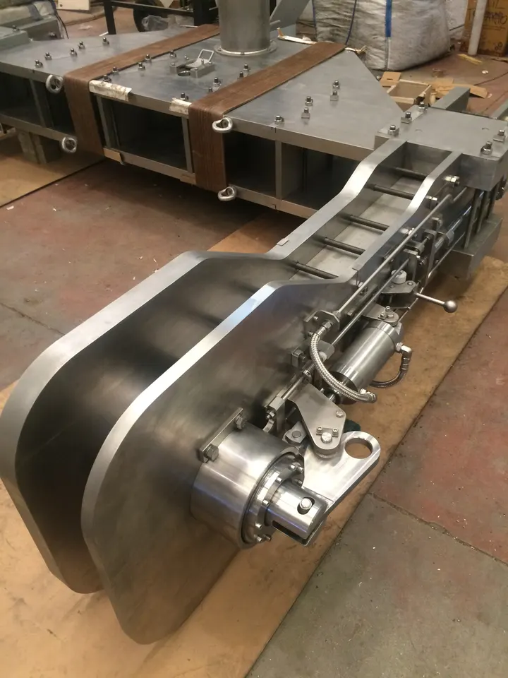
The drawing decides the price before the machine does
Most rejected CNC parts are not rejected because the machine could not hold the feature. They are rejected because the drawing asked for something the part did not need, or because the requirement was ambiguous enough that the supplier and the buyer read it differently. When you outsource milling or turning in Spain, the tolerance callouts on your drawing are a commercial document as much as a technical one: they set the inspection burden, the scrap risk and the delivery date.
The practical rule is simple. Specify the loosest tolerance that still lets the part function, and make every tighter callout earn its place. A drawing covered in tight tolerances by default signals inexperience, and a competent machining partner will either price the risk in or ask questions that delay the job.
This guide covers the tolerances typically seen in CNC milling and turning, how to pick a class based on what the part actually does, how tolerance choice drives cost, and how to communicate requirements so the first article is the last surprise.
Dimensional tolerances: the everyday baseline
Dimensional tolerances control size: a bore diameter, a shaft diameter, a slot width, a distance between features. In general machining practice, a good workshop will hold general tolerances comfortably on most features without special effort, and those general tolerances are usually stated in a drawing block or a title-block note rather than repeated on every dimension.
The trap is the exception. When one dimension carries a much tighter tolerance than the rest, the part moves into a different inspection and process category. That is fine if the feature is functionally critical, such as a bearing seat or a mating pilot. It is wasteful if the dimension was copied from an old drawing or tightened because someone was unsure.
For fits, use the standard fit system your design already follows rather than inventing numeric limits. A shaft and housing fit defined through the appropriate fit designation tells the machinist what the function is, and it keeps the dialogue on the shop floor in familiar terms. Random bilateral limits with no apparent function invite queries and, sometimes, quiet over-machining.
Geometric tolerances: where most disputes begin
Geometric tolerances control form, orientation and location: flatness, straightness, perpendicularity, parallelism, position, concentricity and runout. These are the callouts that most often cause rejections, not because they are hard to machine but because they are hard to interpret when the datum scheme is weak.
A position tolerance without clear datums is an invitation to argument. If the inspector and the machinist choose different reference surfaces, both can be right and the part can still be rejected. Define the datums that reflect how the part is located in the assembly, and keep the datum scheme as simple as the function allows.
Be equally careful with form tolerances that are tighter than the process naturally delivers. A flatness callout on a face that only needs to sit against a gasket is often unnecessary; a perpendicularity callout between two faces that never touch a mating surface adds inspection time for no benefit. Ask of every geometric callout: what would fail in service if this were looser? If there is no clear answer, loosen it or remove it.
Choosing the tolerance class by function, not by habit
Sort the features of your part into three groups. First, critical interfaces: bearing seats, sealing faces, locating bores, threaded connections that carry load. These deserve tight dimensional control and a geometric tolerance that protects the fit. Second, functional but non-critical features: mounting holes, clearance slots, cover faces. General tolerances are usually enough. Third, cosmetic or clearance features: edges, reliefs, non-mating surfaces. Keep these as loose as the drawing standard permits.
This triage has a second benefit: it forces the design intent onto the drawing in a way a machinist can follow. A part with two tight features and everything else general is easy to plan, easy to inspect and easy to quote. A part where everything is tight is planned defensively, inspected slowly and quoted with a risk margin.
When in doubt, talk to the supplier before releasing the drawing. A short conversation about which features actually matter often removes several callouts and shortens the lead time. Good subcontractors would rather ask once than scrap twice.
How tolerance choice drives cost
Tolerance cost is not linear. Moving from general tolerances to tight ones changes the process: more careful setup, slower feeds, additional passes, temperature awareness, more frequent in-process checks and more inspection at the end. Each of those steps adds time, and time is what you are buying.
The same applies to geometric tolerances. A position callout checked on a coordinate measuring machine is a different cost from a callout checked with a gauge on the bench. Tight form tolerances can require stress-relieved stock or a different fixturing strategy, and very tight runout may push a turned part onto a grinder after turning.
There is also a hidden cost in rejections and delays. A part rejected at goods-in ties up transport, admin and production planning, and a replacement run goes to the back of the queue. In practice, the cheapest tolerance is the one that matches the function, because it removes the risk of both over-machining and misunderstanding.
Communicating tolerances so the first article passes
Put the general tolerance note in the title block, state the drawing standard you are following, and let the individual callouts carry only the exceptions. That structure tells the machinist immediately where the special attention belongs.
Define datums explicitly and keep them consistent with how the part is measured. If a feature is inspected in a fixture, say so on the drawing or in the accompanying notes. If the part is thin-walled or prone to distortion, flag it; the machinist can then plan clamping and sequencing rather than discovering the problem at inspection.
Include a clear revision and avoid mixing units or fit systems. Where a requirement is genuinely critical, add a short note explaining the function, for example that a bore is a bearing seat. Machinists respond well to context and poorly to unexplained tight limits.
Finally, agree the inspection basis up front. State whether you will accept on the drawing as written, on a first article inspection report, or on a sampling plan. Disputes usually trace back to an unstated assumption about how the part would be checked, not to a machine that could not hold the tolerance.
A practical conclusion
Specify the loosest tolerance that serves the function, reserve tight dimensional and geometric callouts for the features that truly need them, and make datums and inspection expectations explicit. That discipline reduces rejections, shortens lead times and usually lowers the price without compromising the part.
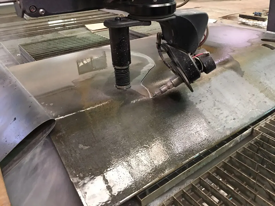
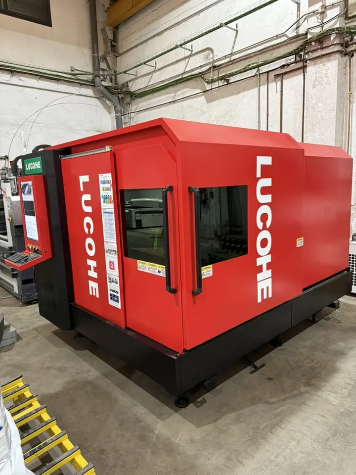
If you are preparing a drawing for milling, turning, waterjet or laser cutting, send it to Cortalia with a short note on what each critical feature does. We will review the tolerances with you, flag anything that looks tighter than the function requires, and quote the job from Coslada for delivery across Spain and the EU.
Have an industrial project?
Our engineering team provides free consultations. We analyze your project and propose the most efficient solution in terms of quality, lead time, and cost.